Theoretical simulations
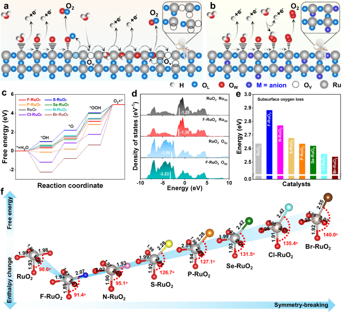
The widely recognized acidic OER mechanism on RuO2 is LOM pathway, in which OL interacts with water–oxygen (OW) to facilitate the formation of O–O intermediate species, concurrently creating OV (Fig. 1a). The generated OV can also serve as active site to accelerate the OER process, ultimately leading to structural collapse and leaching of metal Ru, thus presenting rapid deactivation. In contrast, converting the traditional LOM pathway to a more stable AEM route by anion–induced symmetry–breaking may be a feasible strategy to improve the stability of Ru–based materials (Fig. 1b). Evidently, the oxygen involved comes from water rather than OL, thereby ensuring robust structural integrity during the OER process. Subsequently, DFT simulations were used to accelerate the discovery of high–performance electrocatalysts, thus M–RuO2 (M = F, S, Se, P, N, Cl, and Br) was constructed to evaluate their OER performance. According to the results, a more energy–favorable structural model was adopted for subsequent calculations (Supplementary Figs. 1–7 and Supplementary data 1). The Gibbs free energy of rate–determining step (RDS) for F–RuO2 is 1.80 eV, lower than that of N–RuO2 (1.83 eV), S–RuO2 (1.86 eV), P–RuO2 (2.60 eV), Se–RuO2 (2.76 eV), Cl–RuO2 (3.16 eV), Br–RuO2 (4.28 eV) and RuO2 (1.89 eV) (Fig. 1c and Supplementary Figs. 8–15). In addition, the observed hydrogen bonds between H and adjacent O indicate a low value of the calculated enthalpy change, which serves to stabilize OOH adsorption at the coordinatively unsaturated Ru site on the F–RuO2(110) surface (Supplementary Fig. 16). The charge distinction for the two O species adsorbed on F–Ru and O–Ru is about 0.06 e, which demonstrates the improved O atom binding on F–RuO2(110), thereby fostering the genesis of O−O coupling and ultimately leading to the production of molecular O (Supplementary Fig. 17). Furthermore, the electron localization function (ELF) of the *OOH adsorbed on F–RuO2 surfaces shows a higher ELFmax value than RuO2, which indicates an enhanced covalent bond of OOH intermediate induced by the stronger interaction of *OOH on the F–RuO2 (Supplementary Fig. 18). Moreover, the limiting potential for OER on the F–RuO2(110) surface was estimated at 1.80 V, representing a reduction of approximately 0.11 V compared to RuO2 and implying enhanced OER activity (Supplementary Fig. 19). The outcomes of the calculations revealed that the d–band structure of Ru and the 2p–band structure of O undergo modulation due to the incorporation of F (Fig. 1d). Density of states (DOS) indicates that O 2p band center moves from –2.96 eV (RuO2) to –3.23 eV with the introduction of F, signifying an elevated formation energy for OV, which consequently suppresses the dissolution of Ru in acidic media. Notably, a decrease of the Ru d–band center relative to fermi energy level (Ef) is observed after the partial substitution of O with F, potentially influencing the adsorption/desorption of intermediates on the catalyst surface39. Therefore, compared with the traditional RuO2 following LOM route, the introduction of F gives RuO2 more energy advantages on the AEM path (Supplementary Fig. 20). Furthermore, similar phenomena have been observed on (111) and (100) planes of F–RuO2 and RuO2, proving its universality (Supplementary Fig. 21).

Schematic illustration of a LOM and b AEM route for OER on RuO2 and M–RuO2 surface. (c) Gibbs free energy diagram for different catalysts. d DOS of Ru 3d and O 2p for F–RuO2 and RuO2; corresponding d–band centers are denoted by white lines. e Calculated enthalpy changes for subsurface oxygen loss of various catalysts. f Reaction free energy and subsurface O loss enthalpy change volcano against the symmetry–breaking. The gray, red, blue, pink, yellow, orange, green, cyan and brown balls represent Ru, O, F, N, S, P, Se, Cl and Br atoms, respectively. Source data for this figure are provided as a Source Data file.
To further assess the stability of F–RuO2, the enthalpy of F within bulk C–centered orthorhombic structure was used to compute their chemical potential, indicating resistance to the detachment of F from RuO2 (Supplementary Fig. 22). Additionally, the enthalpy change for subsurface oxygen loss was calculated in Supplementary Figs. 23–30. The enthalpy change of subsurface O loss on the F–RuO2 was significantly higher than that of RuO2 modified by other anions, indicating that symmetry breaking also affects the stability of OL in RuO2 (Fig. 1e). The examination of the enthalpy change associated with the demetallation process of the surface Ru atom from both RuO2(110) and F–RuO2 (110) was evaluated to further investigate the stability (Supplementary Fig. 31). It can be found that the energy expenditure for Ru demetallation elevated from 1.72 to 2.52 eV after the symmetry of octahedral configuration in RuO2 is broken by partial substitution of O with F, indicating increased stability of the surface Ru in F–RuO2 compared to RuO2. It is clear that the Gibbs free energy of the RDS varies with symmetry breaking in an inverted volcano shape (Fig. 1f and Table S1). In contrast, the enthalpy change related to subsurface oxygen loss displays a volcano–shaped profile as a function of symmetry breaking. Note of that F–RuO2 is located at the bottom/top of the volcano due to the presence of high electronegativity but small atomic radius F, which induce slight symmetry breaking in the octahedral configuration of RuO2, consequently reducing the reaction energy barrier and enhancing its stability.
Catalyst synthesis and characterization
Of the candidate electrocatalysts predicted by theoretical calculations, F–RuO2 was considered to be the most promising for OER activity and stability. Therefore, the spherical FC and RuCl3 were ultrasonicated at room temperature (25 °C) and then dried to obtain FC supported RuCl3 (RuCl3/FC) (Supplementary Figs. 32, 33). Subsequently, the F–RuO2/FC was successfully achieved by heat treating the RuCl3/FC at 400 °C in air for 4 h. Scanning electron microscopy (SEM) and transmission electron microscopy (TEM) characterization revealed that the spherical FC emerged with abundant pore structures (Supplementary Fig. 34). However, the intact spherical can be maintained for FC without the addition of RuCl3, indicating that the presence of Ru will accelerate the local pyrolysis of FC and thus lead to a rich pore structure (Supplementary Fig. 35). Therefore, the pyrolysis temperature and time of FC will be ameliorated once Ru is present, thus the specific surface area of F–RuO2/FC can be significantly enhanced as evidenced by N2 absorption–desorption isotherm (Supplementary Figs. 36, 37). In addition, long–range ordered atomic arrangements were successfully detected using a spherical aberration–corrected high–angle annular dark–field scanning TEM (AC–HAADF–STEM) (Fig. 2a). The well–defined lattice spacings (0.22 and 0.18 nm) of (020) and (21\(\bar{1}\)) planes for RuO2 unequivocally indicate the presence of lattice strain compared to RuO2, which may be caused by symmetry breaking due to introduction of heterogeneous atoms (Fig. 2b). The fast Fourier transform (FFT) pattern, inset in Fig. 2b, reveals the exposed (020) and (21\(\bar{1}\)) planes along the [\(\bar{1}\)0\(\bar{2}\)] zone axis of F–RuO2/FC. To confirm the heterogeneous atoms in F–RuO2/FC, STEM energy dispersive spectrometer (STEM–EDS) elemental mappings were conducted in Fig. 2c. In addition to the uniformly distributed Ru and O elements, conspicuous F signals can be observed, suggesting that the lattice strain in F–RuO2/FC may be caused by the incorporation of F. Subsequently, geometrical phase analysis (GPA) was performed to evaluate the strain level and distribution in the F–RuO2/FC. Evidently, the reduced and enhanced strain can be observed along the horizontal (εxx) and vertical (εyy) direction, respectively (Fig. 2d, e). The strain profiles of line1 and line2 acquired from strain mappings further confirm that the compressive stress is predominantly along the εxx direction and the tension stress along the εyy direction (Fig. 2f)40. To investigate the critical insight of chemical distributions for F–RuO2/FC, time of flight secondary ion mass spectrometry (TOF–SIMS) analysis was performed in Fig. 2g. The element intensity versus sputter time reveals that the concentration of O– is notably greater than that of Ru+, being consistent with the characteristics of RuO2. In addition, the detected RuF– signals indicate that F indeed replaces part of O and then bonds with Ru during the heat treatment process. Two–dimensional (2D) TOF–SIMS elemental mappings also confirm the presence of significant RuF– species alongside the abundant Ru and O species (Fig. 2h). Clearly, the distribution of Ru and O signals throughout the space in three–dimensional (3D) TOF–SIMS views indicates that the predominant species is RuO2, consistent with the AC–HAADF–STEM analysis (Fig. 2i). The uniform distribution of RuF– signals throughout the entire 3D space further confirms the partial substitution of O by F, thus leading to the formation of Ru–F bonds. X–ray diffraction (XRD) with Rietveld refinement was conducted to obtain the detailed unit cell parameter (Fig. 2j and Table S2). The sharp diffraction peaks correspond to the tetragonal RuO2 with the space group P42/mnm, indicating that the adsorbed RuCl3 on the surface of FC gradually crystallizes into RuO2 during the heat treatment process. The presence of Ru accelerates the local pyrolysis of FC and resulting in F occupying part of the position of O in F–RuO2/FC (inset in Fig. 2j). The F elements were removed by calcining the FC at 400 °C for 12 h (denoted as (F)C) (Supplementary Fig. 38). Subsequently, M–RuO2/(F)C was successfully prepared by adsorption of RuCl3 on the (F)C combined with heat treatment process (Supplementary Figs. 39–46). Furthermore, the Baur distortion index (Di) was employed to quantify the asymmetry of virtual octahedral units within the RuO2 crystal structure:
$${D}_{{{\rm{i}}}}=\,\frac{1}{6}{\sum }_{{{\rm{i}}}=1}^{6}\left(\frac{|{b}_{{{\rm{i}}}}-\bar{b}|}{\bar{b}}\right)$$
(1)
where \({b}_{{{\rm{i}}}}\) and \(\bar{b}\) represents the individual bond length and the average of six bond lengths, respectively41. Notably, the Di, based on the Rietveld refinement of XRD patterns results, were increase in the order F < N < S < P

a,b spherical aberration–corrected HAADF–STEM images, c STEM–EDS elemental mappings of F–RuO2/FC. Strain mappings of F–RuO2/FC along d εxx and e εyy direction from GPA and f line profiles of strain along the dotted white lines in (d) and (e). g TOF–SIMS depth analysis of Ru+, O–, and RuF– for F–RuO2/FC and h corresponding 2D elemental mapping images and i 3D render overlay images. j XRD pattern of F–RuO2/FC. Inset in (b) and (j) are the FFT pattern and structural model of F–RuO2/FC, respectively. The gray, red and blue balls represent Ru, O and F atoms, respectively. Source data for this figure are provided as a Source Data file.
Subsequently, Raman spectra were carried out in Fig. 3a, where the typical peaks at 506.8, 622.2, and 693.4 cm–1 are attributable to the vibration modes of Eg, A1g, and B2g for Ru–O bonds, respectively42. Compared to RuO2, a noticeable red shift can be observed in the vibration peaks of F–RuO2/FC, which may be caused by the shortened Ru–O bond owing to the partial substitution of O by the highly electronegative F43. Therefore, F 1s XPS spectra of F–RuO2/FC present a wider peak than that of FC, corresponding to the C–F and Ru–F species (Fig. 3b). Furthermore, the content of F in F–RuO2/FC varies with the calcination temperature, which can be confirmed by EDS, XPS, and Raman analysis (Supplementary Figs. 48–54 and Table S9, S10)44,45. Additionally, O 1s XPS peaks of RuO2 are located at 529.0, 530.0, and 531.7 eV, corresponding to OL, OV, and surface–adsorbed H2O, respectively (Fig. 3c)46,47. Evidently, a notable shift of the O species towards higher binding energy can be observed in F–RuO2/FC due to the presence of high electronegativity F results in an altered electronic interaction between Ru and O43. Compared with RuO2, Ru 3p XPS peaks for F–RuO2/FC are negative shift of 0.35 eV, revealing a lower valence state than Ru4+ (Fig. 3d). Furthermore, X–ray absorption near–edge structure (XANES) and extended X–ray absorption fine structure (EXAFS) was executed to scrutinize the electronic structure. The lower absorption energy for F–RuO2/FC compared to RuO2 suggests that the average valence state of Ru in F–RuO2/FC is below +4, which is attributed to the partial substitution of O by highly electronegative F (Fig. 3e). The chemical structure and coordination environment of the F–RuO2/FC was analyzed by Fourier transform of the EXAFS (FT–EXAFS) spectra, where the peak at ~1.42 Å in F–RuO2/FC can be attributed to Ru–O or Ru–F coordination environment (denote as Ru–O/F) (Fig. 3f and Supplementary Fig. 55). Obviously, the diminished intensity of Ru–O/F bonds for F–RuO2/FC as opposed to RuO2 suggests that the introduction of F leads to an unsaturated coordination environment (Table S11). In addition, charge density difference and Bader charge analysis also reveals that the valence state of Ru (+1.34) in F–RuO2 decreases with increasing surrounding electron density, attributing to the electron density surrounding Ru was readjusted as a result of the octahedral symmetry breakdown induced by the highly electronegative F, potentially altering the adsorption of intermediates on RuO2 and thereby switching the reaction route (Fig. 3g–j).

a Raman spectra of F–RuO2/FC and RuO2. b F 1s XPS spectra of F–RuO2/FC and FC. c O 1s and d Ru 3p XPS spectra of F–RuO2/FC and RuO2. Ru K–edge e XANES and f EXAFS of F–RuO2/FC, Ru foil and RuO2. Electron density difference of g F–RuO2/FC and h RuO2. The blue and yellow shaded area mean the electron density accumulation and donation and the isosurface value is 0.065 e/Å3. Bader charge analysis for Ru (gray), F (blue), and O (red) sites of i F–RuO2/FC and j RuO2. Source data for this figure are provided as a Source Data file.
Evaluation of electrocatalytic activity
To verify the prediction of DFT calculation, the catalytic activities of various catalysts towards water oxidation were evaluated using a representative three–electrode setup in 0.5 M H2SO4 (Fig. 4a and Supplementary Fig. 56). Notably, the F–RuO2/FC exhibit a lower overpotential (192, 243, and 296 mV) than those of RuO2/C (230, 306, and 370 mV) and RuO2 (270, 357, and 428 mV) for achieving a current density of 10, 50, and 100 mA cm–2 (Fig. 4a). The rapid OER kinetics of F–RuO2/FC is evidenced by a low Tafel slope value of 41.6 mV dec–1 compared to RuO2/C (69.7 mV dec–1) and RuO2 (76.0 mV dec–1) (Fig. 4b). The OER activities of overpotential and Tafel slope for various catalysts are visually presented in Fig. 4c, where F–RuO2/FC exhibit the smallest overpotential and the Tafel slope value, exhibiting competitive activity among the Ru–based catalysts reported recently (Table S12). Furthermore, electrochemically active surface area (ECSA), which is related to the electrochemical double–layer capacitances (Cdl), was conducted to evaluate the OER activity (Supplementary Fig. 57). The F–RuO2/FC (29.3 mF cm–2) exhibit higher Cdl values compared to RuO2/C (15.6 mF cm–2) and RuO2 (8.9 mF cm–2). Remarkably, the high turnover frequency (TOF) of F–RuO2/FC further confirming that the incorporation of F in RuO2 produced more active sites (Supplementary Fig. 58). In addition, durability is also a crucial factor in assessing their potential for practical application. Therefore, chronopotentiometry tests were performed in Supplementary Fig. 59, where the stability of RuO2/C and RuO2 can be observed to be similar, suggesting that the contribution of existing C towards stability is negligible. Importantly, F–RuO2/FC can operate continuously for over 60 h with slightly dissolution of Ru, indicating that the partial substitution of O by F in RuO2 can significantly improve stability even under harsh acidic conditions (Supplementary Fig. 60). Moreover, the flat polarization curve and fleeting stability prove that FC is inert for OER (Supplementary Fig. 61). It is noteworthy that the activity and stability are closely resemble that of RuO2 when it is mechanically mixed with FC, confirming that the enhanced OER performance of F–RuO2/FC is not caused by the FC substrate (Supplementary Figs. 62, 63). In addition, the lower OER performance demonstrate its sensitivity to the fluorine doping level (Supplementary Fig. 64). Specifically, the Di remains largely unchanged at low F doping levels, while the TOF decreases significantly, suggesting that low F doping primarily affects the number of active sites rather than the Di (Supplementary Figs. 51a, 65). Conversely, as the F doping levels increase, Di increases while TOF decreases, demonstrating that excessive symmetry breaking degrades OER performance (Supplementary Fig. 51b). Similarly, the heat treatment time will also affect the OER activity and stability of F–RuO2 (Supplementary Figs. 66–69). Furthermore, the sharply reduced activity and stability of RuO2/(F)C prove that F is decisive for improving the OER performance of RuO2 (Supplementary Figs. 70, 71). As predicted by the DFT, the RDS energy barrier of OER and the enthalpy change caused by O loss will undergo significant changes when O was replaced by S, Se, P, N, Cl, Br, suggesting that the symmetry–breaking induced by different anions result in varied performance (Supplementary Figs. 72, 73).

a OER polarization curves with 95% iR correction of F–RuO2/FC, RuO2/C, and RuO2 in 0.5 M H2SO4 (pH = 0.3 ± 0.01, scan rate = 5 mV s–1), the resistances of F–RuO2/FC, RuO2/C, and RuO2 are 5.4 ± 0.1 Ω, 5.1 ± 0.2 Ω, and 5.2 ± 0.1 Ω, respectively. b Tafel plots of F–RuO2/FC, RuO2/C, and RuO2. c Histogram of overpotentials at 10 mA cm–2 and Tafel slopes of F–RuO2/FC, RuO2/C, and RuO2. (Error bars represent the standard deviations from three independent measurements) d Polarization curves of PEM electrolyzer with F–RuO2/FC (2 mgRu cm–2) as anode and Pt/C (0.5 mgPt cm–2) as cathode at 80 °C under ambient pressure. e Chronopotentiometry tests of PEM electrolyzer using F–RuO2/FC| |Pt/C as electrocatalysts. All measured in PEM electrolyzers were without iR correction. Source data for this figure are provided as a Source Data file.
Encouraged by the efficient OER performance, F–RuO2/FC and Pt/C were utilized as the anode and cathode electrocatalysts, respectively, to evaluate their practical application potential in the PEMWE device. Specifically, to deliver current densities of 500, 1000, 2000, and 3000 mA cm–2, F–RuO2/FC| |PEM| |Pt/C cell requires voltage as low as 1.58, 1.70, 1.89 and 2.05 V, respectively, which are lower than those of RuO2| |PEM| |Pt/C (1.61, 1.78, 2.10 and 2.42 V) and RuO2/(F)C| |PEM| |Pt/C (1.70, 1.96, 2.44 and 2.86 V) (Fig. 4d and Supplementary Fig. 74a). Subsequently, the chronopotentiometry test was carried out to evaluate the stability of F–RuO2/FC in the PEMWE device (Fig. 4e). Excitingly, the F–RuO2/FC–based cell can operate stably for 2 months even at 100, 500 and 1000 mA cm–2, far surpassing RuO2| |PEM| |Pt/C and RuO2/(F)C| |PEM| |Pt/C, indicating the promising potential for practical applications (Supplementary Fig. 74b, c). Notably, after long–term PEMWE testing, the morphology, chemical states, and crystal structure of F–RuO2/FC remain largely unchanged, in sharp contrast to the severely degraded RuO2/(F)C, proving long–lasting stability (Supplementary Figs. 75–77)48,49. Apparently, F–RuO2/FC present a larger current density and longer stability, exhibiting competitive performance among the recently reported PEM electrocatalysts (Table S13).
Mechanism studies
To investigate the underlying mechanism during the OER process, in situ characterizations were conducted in Fig. 5. Note of that the diffraction peak intensity does not decrease significantly as the potential range from 1.0 to 1.5 V by in situ electrochemical XRD testing, implying the structure of F–RuO2/FC remain intact during a wide range of potential tests (Fig. 5a). More importantly, the well–preserved diffraction peak in the situ monitoring for up to 60 minutes suggests that the O in F–RuO2/FC may not participate in the OER process, thus deviating from the traditional LOM route (Supplementary Fig. 78). Therefore, the dynamic evolution of the surface structure during the OER process is monitored by in situ electrochemical Raman spectroscopy (Fig. 5b). Clearly, the vibrational peaks corresponding to Ru–O bonds (Eg, A1g, and B2g) are evidently present across the entire potential window, suggesting that the structure of F–RuO2/FC is not greatly damaged, consistent with the results of in situ XRD. Significantly, a Raman peak emerges gradually at ~731 cm–1 with the applied potential increases, compared with RuO2/C, attributed to the formation of Ru–OOH intermediates in the AEM pathway (Supplementary Fig. 79)50. As shown in Fig. 5c, the corresponding contour plots exhibit significantly enhanced vibration signals of B2g for Ru–OOH intermediates except for the predominant feature signals of Ru–O bonds, proving that the reaction intermediates in the AEM pathway are indeed captured.

a In situ XRD patterns, b in situ Raman spectra and c corresponding contour plots, d in situ ATR–IR spectra of F–RuO2/FC. e DEMS signals of 32O2, 34O2, and 36O2 from the gaseous products for 18O–labeled F–RuO2/FC catalysts in H216O aqueous H2SO4 electrolyte during three times of LSV cycles. f Schematic illustration of the mechanism transformation from lattice oxygen mechanism (LOM) to adsorption evolution mechanism (AEM) caused by F–mediated symmetry breaking on RuO2. Source data for this figure are provided as a Source Data file.
To further elucidate the actual OER route, in situ attenuated total reflectance infrared (ATR–IR) spectroscopy was carried out to detect the reaction intermediates. As shown in Supplementary Fig. 80, two absorption peaks attributed to the *OO intermediate formed during the LOM pathway are detected, indicating that RuO2/C follow the conventional LOM pathway during the acidic OER process51. Conversely, in situ ATR–IR spectroscopy of F–RuO2/FC showed a sharp characteristic peak appear at 1237 cm–1, belonging to the stretching vibration of surface–adsorbed *OOH intermediates, evidencing the dominance of the AEM pathway (Fig. 5d)52. Obviously, the signals of *OOH intermediates gradually appear and are significantly enhanced with the increase of potential, indicating that the incorporation of F can force the reaction mechanism of RuO2 from the traditional LOM to AEM, thus ensuring long–lasting stability even at high applied potential. Additionally, F–RuO2/FC show clearly pH–independence, suggesting the significant suppression of the LOM pathway and the dominant role of the AEM pathway (Supplementary Fig. 81)53,54. Furthermore, the reaction intermediate signals of *OOH in the AEM pathway and *OO in the LOM pathway were simultaneously detected during the OER process of N–RuO2/(F)C and S–RuO2/(F)C, but the signals of *OOH are disappeared across the entire potential window of P–RuO2/(F)C, Se–RuO2/(F)C, Cl–RuO2/(F)C and Br–RuO2/(F)C (Supplementary Fig. 82)55. Subsequently, operando differential electrochemical mass spectrometry (DEMS) was performed on 18O isotope–labeled F–RuO2/FC using linear sweep voltammograms (LSV) in H216O–0.5 M H2SO4 (Supplementary Fig. 83a). As shown in Fig. 5e, the mass signals of 32O2 and 34O2 were detected without 36O2 products, suggesting the non–participation of OL in the OER process56. The mass signals of 32O2 gradually increase and present a constant ratio (34O2:32O2) with the occurrence of OER, further demonstrating the dominant AEM pathway (Supplementary Fig. 83b, c). Therefore, it can be concluded that the LOM pathway that OL is involved in the OER process, including a labeled 18O and an ambient O (16O) from the electrolyte, resulting in the instability surface of the RuO2 and consequently generating 16O18O species (Fig. 5f). Based on the DFT computations and detailed experimental characterization, the F induced symmetry–breaking in octahedral configuration of RuO2 improves the interaction between adsorbent and the electrocatalysts surface, alters the OER route to follow the AEM pathway, and ultimately enhancing the electrocatalytic performance.
In summary, a highly efficient acidic OER electrocatalyst has been predicted by DFT calculation, which uses F to replace partial O in RuO2 to break the symmetry of the octahedral configuration and thus switch the reaction path. The improved O species adsorption and attenuated demetallation process of Ru improve the OER intrinsic activity and resistance to solvation. As a validation, to deliver the current density of 10, 50, and 100 mA cm–2, only overpotentials of 192, 243, and 296 mV need to be provided for F–RuO2/FC in acidic conditions. More importantly, the cell voltage of 1.58, 1.70, 1.89 and 2.05 V can drive current densities up to 500, 1000, 2000, and 3000 mA cm–2, respectively, simultaneously continuously operating at 100, 500 and 1000 mA cm–2 for 2 months in a PEMWE device. Detailed in situ experiments reveal that the F–induced symmetry–breaking ensures the structural stability of RuO2 during the OER process and changes their traditional OER mechanism from LOM to AEM pathway, thus enhancing the stability. This study offers a fresh perspective for altering the reaction mechanism of OER electrocatalysts based on anion–induced symmetry–breaking to realize efficient performance.