Synthesis and characterization of Ru/CoFe-LDHs
The monatomic ruthenium (Ru) anchoring on the cobalt iron LDHs (CoFe-LDHs) catalyst was performed via a simple two-step procedure. Firstly, CoFe-LDHs nanosheets as precursor was prepared by a co-precipitation process at room temperature (Supplementary Figs. 1 and 2, details in the “Experimental section”). Then the CoFe-LDHs precursor was added slowly into a 0.6 mM ruthenium chloride solution with pH tailored to 12. After stirring at room temperature for 12 h, the Ru anchoring on CoFe-LDHs (denoted as Ru/CoFe-LDHs) could be fabricated (Fig. 1a). The ruthenium content of Ru/CoFe-LDHs was 0.45 wt.% determined by the inductively coupled plasma (ICP) analysis. The morphology of Ru/CoFe-LDHs (Fig. 1b and Supplementary Fig. 2) was the same as the CoFe-LDHs nanosheets showing a clean surface without any agglomeration. The inset of Supplementary Fig. 1 and Fig. 1b showed the selected area electron diffraction (SAED) patterns of CoFe-LDHs and Ru/CoFe-LDHs nanosheets respectively, which both showed (100) and (110) diffraction rings of CoFe-LDHs. The X-ray diffraction (XRD) was also employed to further study the crystal structure before and after loading Ru on the surface of CoFe-LDHs (Supplementary Fig. 3). The data reveal characteristic diffraction patterns of LDHs structure without any other impurities and the interplanar spacing in the thickness direction is 0.75 nm derived from (003). Combining with the HR-TEM images (Supplementary Fig. 4), the layer number of LDHs could be calculated as which was corresponding to ~10 layers of edge sharing octahedral MO6 structure.

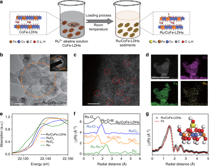
Synthesis and structure characterizations of Ru/CoFe-LDHs. a Schematic illustration of the hydrolysis-deposition to form Ru/CoFe-LDHs. b Transmission electron microscopy (TEM) images of as-prepared Ru/CoFe-LDHs nanosheets and inset shows the corresponding SAED pattern of Ru/CoFe-LDHs nanosheets marked in orange circle, showing characteristic diffraction rings of LDHs. Scale bar, 50 nm. c The Cs-corrected STEM image of Ru/CoFe-LDHs nanosheets shows the monoatomic ruthenium dispersed on the surface of LDHs (some of the isolated Ru atoms are marked with red circles). Scale bar, 2 nm. d The HAADF-STEM images of the Ru/CoFe-LDHs and corresponding elemental distribution maps of Ni, Fe, and Ru in the Ru/CoFe-LDHs. Scale bar, 50 nm. e The XANES spectra and f Fourier-transformed Ru K-edge EXAFS spectra of Ru/CoFe-LDHs, RuCl3, RuO2, and Ru metal. g Corresponding model-based fittings of Ru EXAFS for Ru/CoFe-LDHs and simulated EXAFS spectra from Ru–O and Ru–O–M (M = Co or Fe) bonds (the inset is the magnifying local structure of Ru/CoFe-LDHs), showing the exclusive existence of Ru–O–M bonds in Ru/CoFe-LDHs sample
The spherical aberration corrected scanning transmission electron microscope (Cs-corrected STEM) (Fig. 1c) clearly showed Ru atoms individually dispersed on the surface of CoFe-LDHs. In addition, high-angle annular dark field-scanning transmission electron microscopy (HAADF-STEM) image and corresponding elemental mapping confirm that the Ru element was uniformly distributed with the cobalt and iron elements, and no local aggregation of Ru can be observed (Fig. 1d). The valence states and local coordination structure of the ruthenium atoms on the Ru/CoFe-LDHs nanosheets are critical for their catalytic activity, here Ru K-edge X-ray absorption near edge structure (XANES) (Fig. 1e and Supplementary Fig. 5) clearly reveals that the Ru K edge position (22129.47 eV) of Ru/CoFe-LDHs was in-between that of RuO2 (22132.36 eV) and metallic Ru (22127.48 eV). Further fitting (Supplementary Fig. 6) indicates that the oxidation state of Ru in Ru/CoFe-LDHs is 1.6+. The local structure can be revealed by the Fourier-transformed extended X-ray absorption fine structure (EXAFS) spectrum of Ru/CoFe-LDHs (Fig. 1f). When comparing with Ru metal, RuCl3 and RuO2, Ru/CoFe-LDHs shows no characteristic peaks corresponding to Ru–Cl bond, metallic Ru–Ru bond and Ru–O–Ru bond from clustered ruthenium oxides. Only the first-shell Ru–O bond and some weak Ru–O–M (M = Co or Fe) can be identified (Fig. 1g and Supplementary Fig. 7). The absence of Ru–Cl in Ru/CoFe-LDHs excludes RuCl3 residuals, indicating the RuCl3 has fully hydrolyzed to form hydroxyl complexes and anchored on the surface of CoFe-LDHs via dehydration reaction34. The absence of Ru–O–Ru bonds excludes the existence of RuO2. These, in combination with Cs-corrected STEM, further confirmed that Ru atoms in Ru/CoFe-LDHs are indeed atomically dispersed. Moreover, model-based EXAFS fitting (Supplementary Table 1) further confirms that each Ru atom is coordinated with 3.9 ± 0.7 oxygen atoms, in which 2.9 ± 0.6 Ru–O were bonded nearby metal (Co or Fe). This means Ru was located on the surface of the CoFe-LDHs with isolated single atomic structure (schematically shown in the inset of Fig. 1g) instead of agglomeration or within the MO6 laminates.
X-ray photoelectron spectroscopy (XPS) experiments were performed to measure the chemical compositions and electronic properties of the electrocatalysts, as showed in Supplementary Fig. 8 and Fig. 2. Ru/CoFe-LDHs shows the binding energy of Ru 3p3/2 and Ru 3p1/2 at 461.7 eV and 483.8 eV, respectively (Fig. 2a), which is higher than those of Ru (0) 3p3/2 and Ru (0) 3p1/2 while lower than those of Ru (III) 3p3/2 and Ru (III) 3p1/2 (as showed in Supplementary Fig. 9). The electronic structure measured by XPS is consistent with the XANES results in Fig. 1e, indicating a special state (1.6+) of Ru in Ru/CoFe-LDHs. Furthermore, XPS quantitative analysis (Supplementary Table 2) shows that the surface concentration of Ru in Ru/CoFe-LDHs is about 0.42 wt.% which is very close to the ICP-MS result (Supplementary Table 3, 0.45 wt.%). In comparison with pure CoFe-LDHs, the binding energies of Co 2p3/2 in the Ru/CoFe-LDHs nanosheets negatively shifted from 779.9 to 779.4 eV (Fig. 2b), revealing the electron deficient state of cobalt sites. In contrast, the binding energy of Fe 2p3/2 in Ru/CoFe-LDHs had a positive shift of ~0.7 eV compared with that in CoFe-LDHs (Fig. 2c). The O 1s spectrum (Fig. 2d) suggested the appearance of bond between oxygen and ruthenium on the surface of Ru/CoFe-LDHs due to formation of Ru–O–M (M stands for Fe or Co) bond as schematically shown in the inset of Fig. 1g. The increase of metal (Co or Fe) valence could be attributed to the noble metallic Ru with higher electronegativity attracting more electrons through the Ru–O–M bonds, which was in accord with the fact that Ru possess a valance state lower than its initial salt RuCl3, suggesting the transfer of electrons from Co or Fe to Ru by bridging O. The computational simulation (Fig. 2e) further confirmed that the charge density of Co and Fe atom of Ru/CoFe-LDHs were lower than those of CoFe-LDHs indicating the introduction of Ru could reduce the electron cloud density of Co and Fe, which was in line with the XPS analysis. At the same time, the bandgap between the valence and conduction bands of Ru/CoFe-LDHs was narrower than that of CoFe-LDHs (Supplementary Fig. 10) after loading of single atomic Ru, which means Ru/CoFe-LDHs has a better conductivity. The combination of the XPS, XAS, and computational simulation results further validated the strong electron coupling between monoatomic Ru catalysts with CoFe-LDHs support, which would definitely play a strong influence on the electrocatalytic activity and stability.

The strong synergetic coupling between Ru and LDHs in the Ru/FeCo-LDHs catalysts revealed by XPS. a The high-resolution X-ray photoelectron spectroscopy (XPS) of Ru in the Ru/CoFe-LDHs nanosheets. b–d The XPS spectra of Co (b), Fe (c), and O (d) in the CoFe-LDHs and Ru/CoFe-LDHs nanosheets. Figure a, b, c, and d has different intensity scale bars. e The differential charge density of elements in CoFe-LDHs and Ru/CoFe-LDHs from computational simulation, revealing electron donation from LDHs to Ru
Electrochemical performance of Ru/CoFe-LDHs
The electrocatalytic activity of Ru/CoFe-LDHs toward OER in 1.0 M KOH solution was measured and normalized by geometric surface area alongside with CoFe-LDHs and commercial RuO2 catalysts (loading: 1 mg cm−2). Figure 3a shows the linear sweep voltammetry (LSV) polarization curves of OER on different catalytic electrodes. Notably, the overpotential (η10) of Ru/CoFe-LDHs was 198 mV, which is 112 mV and 202 mV lower than those of CoFe-LDHs and the commercial RuO2, respectively. Meanwhile, the current density of Ru/CoFe-LDHs at potential of 1.5 V vs. RHE was 214 mA cm−2, which was ~45-fold higher than that of CoFe-LDHs (Supplementary Fig. 11). The Tafel slopes of the Ru/CoFe-LDHs, CoFe-LDHs and RuO2 were shown in Fig. 3b. The Ru/CoFe-LDHs has a Tafel slope of 39 mV dec−1, which was lower than 59 mV dec−1 for CoFe-LDHs and 78 mV dec−1 for RuO2, implying the favorable OER kinetics for monatomic Ru/CoFe-LDHs catalyst. The Nyquist plots of Ru/CoFe-LDHs, CoFe-LDHs, RuO2, and carbon paper at the overpotential of 100 mV were shown in Supplementary Fig. 12, indicating that Ru/CoFe-LDHs had smaller charge transfer resistance than that of CoFe-LDHs, implying that the monatomic Ru anchoring on CoFe-LDHs with the improvement of intrinsic electrocatalytic activity. In all, as listed in Supplementary Table 4, our Ru/CoFe-LDHs is highly efficient among the best OER catalysts. Moreover, the Ru/CoFe-LDHs catalyst has a higher catalytic activity than the benchmarking RuO2 catalysts and NiFe-LDHs array with noble metal doping41,42, while the usage of noble metal is <10% of them (Fig. 3c)43,44. In Supplementary Fig. 13, there were some nanoparticles (cluster or aggregation) on the CoFe-LDHs surface with higher Ru loading, which caused performance degradation. With decreasing amount of noble metal from the optimized point, the as-prepared catalysts showed slower current density increase though still possessed the same intrinsic activity, which can be explained by the decreasing amount of Ru active sites (Supplementary Fig. 14). The MgAl-LDHs, NiCo-LDHs and NiFe-LDHs were also selected as supports for the monatomic Ru via the same synthesis method, and the corresponding electrocatalytic performances (η10 (Ru/CoFe-LDHs) (~198 mV) < η10 (Ru/NiFe-LDHs) (~220 mV) < η10 (Ru/NiCo-LDHs) (~240 mV) < η10 (Ru/MgAl-LDHs) (~290 mV)) were shown in Fig. 3d, further confirmed that the LDHs played a major role in the improvement of OER catalytic performance. While transition metal ions with d-electrons can donate a certain number of electrons to Ru atoms, Mg2+ and Al3+ from the main group are without d-electrons thus the Ru atoms are hard to attract electrons from them, which in turn limiting the electronic coupling effect in between. For transition metal based LDHs substrate, an elementary combination with smaller electronegativity can possess stronger electronic coupling with Ru, result in better OER catalytic performance. Based on the sequence of electronegativity (Fe (1.83) < Co (1.88) < Ni (1.92)), atomic Ru on the binary CoFe-LDHs substrate is expected to have the best OER performance, which is also confirmed by our electrochemical analysis (Fig. 3d).

High OER performance of Ru/CoFe-LDHs electrocatalyst. a Comparison of iR compensated polarization curves of Ru/CoFe-LDHs with CoFe-LDHs, Carbon paper and the commercial RuO2 catalyst. The η10 stands for the overpotential with current density of 10 mA cm−2. b The corresponding Tafel plots of the three catalysts. c The comparison of OER overpotentials and Ru contents in different catalysts at a current density of 10 mA cm−2. d The iR compensated polarization curves of Ru/CoFe-LDHs, Ru/NiFe-LDHs, Ru/NiCo-LDHs and Ru/MgAl-LDHs. The polarization curves are collected at the scan rate of 1 mV s−1. e The potentiostatic curves of different catalyts under a certain overpotential for initial current density of 200 mA cm−2, in which Ru/CoFe-LDHs demonstrating unprecedented high stability. f UV–vis spectrum and inset digital photographs for alikaline electrolytes after long-term stability test of electrocataysts, in which Ru/CoFe-LDHs working as OER catalysts shows much higher stablility over RuO2. g The concentration of metal content in alikaline electrolytes after stability test. The Ru mass loading in each electrode was comparable
Stability was a crucial criterion to evaluate the performance of catalysts, especially for monatomic metal catalysts. The monatomic Ru/CoFe-LDHs electrocatalyst during repeated cycling in 1.0 M KOH electrolyte was further evaluated, which exhibited no obvious loss of activity after 1000 CV cycles sweeping between 1.35 and 1.5 V vs. RHE (Supplementary Fig. 15). When operating the OER test at a constant potential (Fig. 3e), the current density of Ru/CoFe-LDHs maintained 99% after 24 h test, which was much better than that of CoFe-LDHs (90% after 12 h test) and RuO2 (64% after 10 h). In addition, the color of electrolyte with RuO2 electrocatalyst turned pale yellow after stability test due to the dissolution of RuO2 into alkaline solution9,45, while the color of electrolyte with Ru/CoFe-LDHs had no obvious change (inset of Fig. 3f). UV–vis spectrum of RuO2 electrolyte shows two obvious peaks at 274 and 371 nm corresponding to hydrated Run+ ions (n > 4), while no absorption peak with Ru/CoFe-LDHs electrolyte (Fig. 3f). To confirm Ru/CoFe-LDHs is more stable than RuO2 under OER working condition, Ru/CoFe-LDHs electrode (2 mg cm−2) alongside with two control catalytic electrodes, namely, RuO2 (0.012 mg cm−2) electrode, RuO2 (0.012 mg cm−2) and CoFe-LDHs (2 mg cm−2) mixture electrode were specifically prepared with the similar Ru mass loading. After the long-term stability test, we detected the metal dissolution amount in the electrolyte by ICP-MS measurement. Although ruthenium dioxide with a small mass loading (0.012 mg cm−2) with the identical Ru amount of Ru/CoFe-LDHs, from ICP-MS results (Supplementary Table 3 and Fig. 3g), we can note that ca. 86 ppb of Ru can be detected in the electrolyte, corresponding to ~70% Ru element used in the catalyst. In contrast, Ru content in electrolyte for Ru/CoFe-LDHs electrode is below the detection limit of ICP-MS (DL, 0.005 ppb), indicating the single-atomic Ru on the surface of CoFe-LDHs is much more stable than RuO2 bulk under the OER working condition. Besides, the RuO2 and CoFe-LDHs mixed electrode also show ca. 53 ppb of Ru dissolved in the electrolyte, which is still much higher than Ru/CoFe-LDHs and further confirms the strong electronic coupling between atomic Ru and CoFe-LDHs plays a critical role in enhancing the stability of Ru catalyst during OER process. Before and after loading of atomic Ru on the surface of CoFe-LDHs, the catalysts have different cyclic voltammetry (CV) curves in the pseudocapacitive region (Supplementary Fig. 16), and they are also different from those reported in the previous literature of RuO246,47,48. After loading atomic Ru onto CoFe-LDHs, it shows a pair of broad and overlapped redox peaks after 1.0 V preceding OER, which corresponds to the pre-oxidation of Ru and Co/Fe. Compared with CoFe-LDHs, the redox peak shifted to a lower potential alongside with better OER activity, which might mean the active site of Ru/CoFe-LDHs promoting OER kinetics could be more easily activated in the pre-oxidation process due to the strong electronic coupling between Ru and CoFe-LDHs. In addition, electric double layer capacitance (Cdl) was calculated to estimate the electrochemical active surface area (ECSA)49,50 by measuring the CV curves in the double layer capacitance region without obvious redox processes at different scan rates (Supplementary Fig. 17). The Ru/CoFe-LDHs had a little larger ECSA (1150 μF cm−2) than CoFe-LDHs (1089 μF cm−2), suggesting the reliability of OER activity comparison. After the long-term stability test, the CV curve (Supplementary Fig. 16) and ECSA of Ru/CoFe-LDHs (1147 μF cm−2) had no obvious change indicating the monatomic structure is stable in the OER process. Moreover, the TEM image in Supplementary Fig. 18 and Cs-corrected STEM image in Supplementary Fig. 19 further highlighted that the distribution state of monoatomic Ru atom on CoFe-LDHs surface has no obvious change after long term stability test. XPS measurement of Ru/CoFe-LDHs after stability test shows some predictable changes (Supplementary Fig. 20), namely, the valence states of all the metallic elements, including Co, Fe and Ru, had relatively increased after working at a high potential, but keeping Ru valance state far less than 4+. The high-resolution XPS of O 1s (Supplementary Fig. 20d) suggested there were oxyhydroxide (MOOH, 535 eV)51 and adsorbed H2O (532 eV)52 on catalyst surface after OER measurement. The XPS quantitative analysis showed that the surface concentration of Ru had no obvious change after long term stability test (Supplementary Table 2 and 5). All of the above electrochemical tests showed that the Ru/CoFe-LDHs catalyst has outstanding OER activity as well as superior stability, evidencing that anchoring single atomic ruthenium on CoFe-LDHs support with strong synergetic coupling could indeed promote the electrocatalytic performance towards OER in alkaline condition.
In situ and operando XAS analysis of Ru/CoFe-LDHs
To further understand the interplay of monatomic Ru atoms and CoFe-LDHs in the Ru/CoFe-LDHs catalyst regarding OER activity and stability, in situ and operando XAS53,54,55,56,57 was performed to probe the structural and oxidation state changes of these elements under the electrochemical conditions. During the in situ XANES measurement, the potential was firstly increased from open-circuit voltage (OCV) to 1.6 V vs RHE, and then decreased back to OCV. XAS spectra were record at each potential that was held around 15 min before the measurement to enable the thermodynamic stable stage. As shown in Fig. 4a, b, Ru XANES edge shifted to higher energy when the applied potential increased to 1.6 V, suggesting that Ru was oxidized to higher oxidation state during OER reaction. However, the oxidation state was still below 4+, as comparing to the XANES of RuO2 in Fig. 4a, b. This means that the single atomic Ru in Ru/CoFe-LDHs catalyst will not transform into an unstable phase of Ru(4+δ)+ (δ > 0) during OER reaction, which can cause the dissolution of Ru and degradation of RuO2 based catalysts9,45,58. Interestingly, when the applied potential returned to OCV, Ru XANES edge shifted back to lower energy around initial edge. Although the XANES edge did not overlap with the initial OCV one, the reversible change of Ru valence state was a good indication of its active contribution in the catalytic reaction for OER. Comparatively, under OCV conditions, both Co and Fe shows higher edge energy when compare with Co(II) and Fe(III) (Fig. 4c, d), which means Co and Fe have higher oxidization state than 2+ and 3+, respectively, and is in consistence with the XPS results (Fig. 2b, c). As the potential is increased to 1.6 V, a clearly edge shift appears in both Fe and Co spectra, indicating the further oxidization of Fe and Co (Fig. 4c, d). However, when switching the electrode potential back to OCV, the Fe and Co edges show no change (Fig. 4c, d). This is different from Ru and is a sign for the irrevesible change of Co and Fe, which might be due to the strong adsorption of intermediate group on the Co or Fe sites59.

Operando XAS measurement of Ru/CoFe-LDHs. In situ XANES under the electrochemical condition of (a, b) Ru K-edge (c) Co K-edge (e) Fe K-edge. R-space fitting curves of Co (d) and Fe (f) EXAFS at the reaction potential of 1.6 V, evidencing that valance of Ru is always kept <4+ even under high overpotential. g The schematic illustration of Ru/CoFe-LDHs catalyst during OER. OCV represents open-circuit voltage
To probe the local structure changes besides valance states, we performed in situ EXAFS measurements. At the reaction potential of 1.6 V, all Co (Fig. 4d and Supplementary Fig. 21), Fe (Fig. 4f and Supplementary Fig. 22) and Ru (Supplementary Fig. 23) exhibit a clearly structure change. However, neither Co nor Fe local strutures can be reversible when the electrode potential back to OCV. From the model-based analysis (Fig. 4d, f and Supplementary Table 1), we can see that the bonding lengths of Co–O, Co–O–Fe, Co–O–Co, Co–O–Ru, Fe–O, Fe–O–Co, and Fe–O–Ru all shrink at certain degree during the OER reaction and the changes are irreversible. This shrinkage in bonds could further fix Ru atomic structure on the surface, thus avoiding possible dissolution during oxidation state variation when faciliating OER. This can also improve the stability of Ru single-atom catalyst and could be one reason that Ru did not exceed 4+ during the reversible changes in OER. The reaction induced structure is different from the initial as-synthesized structure shown in Fig. 1 and can only be observed through our in situ and operando investigation. In addition, this Ru/CoFe-LDHs interactions can be regarded as the synergistic effect between the active Ru catalytic site and the CoFe-LDHs support. The support effect has been observed in many reports for thermal catalysts60,61,62,63, and is believed to be helpful for catalyts to achieve remarkable activity, stability, and selectivity64,65. It is noteworthy that the Ru local structure does reconstruture when the electrode potential goes back to OCV (Supplementary Fig. 23), namely, the Ru k-space EXAFS show clearly reversible structural changes: the red line (at 1.6 V) in Supplementary Fig. 23 shifted to right as comparing to the black line (initial) and then went back to the initial state when the applied potential was changed to OCV. Both operando XANES and EXAFS show the reversibility of Ru and irreversibility of Fe and Co, indicating that Ru works as the active site in the monatomic Ru/CoFe-LDHs and the importance of support. Based on those measurements, we summarized a schematic drawing for above processes in Fig. 4g to show the concurrent changes of Ru, Fe, Co in OER reactions.
Theoretical calculations
To further rationalize the improved OER performance and identify the active site of the Ru/CoFe-LDHs catalyst, first principles density functional theory plus Hubbard U (DFT + U) caclutation was employed to simulate the OER process based on the 4e-mechanism proposed by Norskov on CoFe-LDHs and Ru/CoFe-LDHs structure models. Ru/CoFe-LDHs was considered as loading the ruthenium hydroxyl complex on the (001) crystal plane of CoFe-LDHs by releasing one water molecule and the Ru atom coordinates with five oxygen atoms simulating the increase of oxidation state (considering the Ru would be pre-oxidized before OER basing on the operando EXAFS and CV results) as the corresponding optimized structures shown in Supplementary Figs. 24 and 25. Since the edge sites of LDHs had a relatively high OER catalytic activity, consequently, for DFT + U computations, the Fe atoms in the edge of CoFe-LDHs and the Ru atoms on the plane surface were selected as active sites, respectively. Proposed 4e-mechanism of OER and the optimized structures of the intermediates in the free-energy landscape of CoFe-LDHs and Ru/CoFe-LDHs were presented in Fig. 5. For CoFe-LDHs and Ru/CoFe-LDHs structures, the OER rate determining step was found to be the formation of *OOH group from *O group (step III). Moreover, by comparing the free-energy plots in Fig. 5c, d and Supplementary Fig. 26, we found the Ru atom sites on the surface of CoFe-LDHs showed a lower Gibbs free energy (1.52 eV) of the rate determining step than that of the Fe atom sites on the edge of CoFe-LDHs (1.94 eV) and Ru atom sites on (110) face of RuO2 crystal (1.59 eV)66, revealing a more favorable OER kinetics in Ru/CoFe-LDHs structures and the monoatomic Ru atoms on CoFe-LDHs were efficient active sites to catalyze OER. When Fe ion in (100) crystal plane of Ru/CoFe-LDHs was selected as active site for DFT + U calculation (Supplementary Fig. 27), the overpotential was even larger (0.94 eV) than that of pure CoFe-LDHs (0.71 eV) or Ru active site in Ru/CoFe-LDHs (0.29 eV), which confirmed the shift of OER active sites from CoFe-LDHs to Ru atoms on the surface of CoFe-LDHs. Furthermore, the Ru atoms in Ru/MgAl-LDHs, Ru/NiCo-LDHs, and Ru/NiFe-LDHs with identical structure were selected as active sites for DFT + U calculation to acquire the overpotentials, and the overpotentials were in the order of ηRu/CoFe-LDHs (0.29 eV) < ηRu/NiFe-LDHs (0.75 eV) < ηRu/NiCo-LDHs (0.97 eV) < ηRu/MgAl-LDHs (1.09 eV) as showed in Supplementary Fig. 28, which meant that Ru on CoFe-LDHs had the most favorable kinetic toward OER among these binary metal LDHs supported Ru catalysts. The cacualtion results were in good consistent with the experimental OER activity data (Fig. 3d), further highlighted the prominent role of LDHs in the improvement of catalytic performance. Therefore, the theory and experiment were in agree that the OER kinetics could be facilitated by dispersing the single atomic ruthenium on CoFe-LDHs support with strong synergetic coupling which significantly enhanced intrinsic electrocatalytic activity and stability.

Theoretical OER overpotential for CoFe-LDHs and Ru/CoFe-LDHs. Proposed 4e-mechanism of oxygen evolution reaction on CoFe-LDHs (a) and Ru/CoFe-LDHs (b) for DFT + U calculation. The Fe ion (*) in CoFe-LDHs and the Ru (*) coordinating with five oxygen atoms on Ru/CoFe-LDHs are the active sites. Gibbs free-energy diagram for the four steps of OER on CoFe-LDHs (c) and Ru/CoFe-LDHs (d). The green box step is the rate determining step and η stand for overpotential. The lower activation Gibbs free energy of Ru/CoFe-LDHs predicts more favorable OER kinetics
Designing single atom catalysts to trigger the sluggish OER reaction is a promising strategy to balance the adsorption/desorption behavior of the intermediates for this complicated 4e transfer process. Some pioneering work focused on anchoring transition metal atoms into C/N structures, such as Fe/N/C67. But this kind of material suffer durability issue during the highly oxidative OER process, especially at high current density conditions. From this respect, embedding single transition metal into oxides/hydroxides is a better choice. For example, Chen et al.41 synthesized NiFe-LDHs with Ir4+ doping in the LDHs laminate, Feng et al.42 fabricated Ru doped NiFe-LDHs, and Liu et al.68 anchored Pt atoms into NiO crystals. Despite the cost of Pt and Ir are high and the performances are still not comparable to the state-of-the-art, one risk is that Pt/Ir/Ru atoms are able to be oxidized to >4+ in these cases, which are easily migrating into the electrolyte. Anchoring inert Au atoms on LDHs did not face the stability issue, but Au are also inert to OER and could only be used to tune the electronic structure of the nearby Fe sites35. Different from those pioneering work, single atom Ru, which was coordinately anchored and stabilized on the redox active LDHs surface in this work. The strong electronic coupling interaction between Ru and CoFe-LDHs tuned the electronic and coordination state of Ru, allow Ru atoms to exist at a valence state of 1.6+ while stably work below 4+ without facing the dissolution problem. This coordination based electronic coupling strategy for single atom catalysts might also be applicable to other systems.