Synthesis and structural characterization
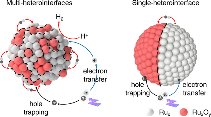
The designing of the photocatalytic H2 evolution system was schematically illustrated in Fig. 1. Through the strategy of in-situ oxygen impregnation, we homogeneously integrated the amorphous Ru and RuOx species into a hybrid-nanoparticle at the atomic scale, and thus creating multiple heterointerfaces. The amorphous RuOx sites generated in situ were designed for hole trapping, while the amorphous Ru sites were designed as the electron acceptor for catalytic reaction. As such, compared with the traditional heterojunction with single heterointerface and few contact surfaces, the photogenerated electrons and holes from g-C3N4 support can be effectively separated, and the reduction/oxidation reactions can be decoupled spatially, on such atomically homogeneous Ru-RuOx amorphous hybrid-structure. The preparation of amorphous Ru and Ru-RuOx nanoparticles anchored on g-C3N4, named RCN and RRCN, respectively, was represented in Fig. 2a (for details see “Methods”). Starting from bulk g-C3N4 obtained by thermal polymerization of urea, the RCN photocatalyst was synthesized by calcinating ruthenium carbonyl (Ru3(CO)12) which was fully adsorbed on ultra-thin g-C3N4 nanosheets (Supplementary Fig. 1). Subsequently with a partial oxidation process, the RRCN as a H2 evolution photocatalyst was successfully constructed. The Ru content for RCN and RRCN was determined to be ~1.5 wt% according to the inductively coupled plasma optical emission spectrometry (ICP-OES) analysis.

Schematic illustration of the solar-driven H2 evolution system on Ru-RuOx/C3N4 with multiple and single hetero-interface.

a Schematic illustration of the preparation strategy for RCN and RRCN. b–e HAADF-STEM, SEAD (inset), and high-resolution AC-HAADF-STEM images of RCN (b, c) and RRCN (d, e), respectively. f AC-HAADF-STEM image and near atomic resolution mappings of RRCN. g k2-weighted Fourier transform (FT) Ru K-edge EXAFS spectra for RCN, RRCN and Ru foil and RuO2 (no phase correction).
In order to examine the morphology and structure of Ru species in the photocatalysts, transmission electron microscopy (TEM) was first carried out. As shown in Fig. 2b and Supplementary Fig. 2, the Ru nanoparticles in the RCN sample with an average diameter of 3.8 nm were uniformly dispersed on the g-C3N4 nanosheets (CN). As shown in the Aberration-corrected high-angle annular dark-field scanning transmission electron microscopy (AC-HAADF-STEM) image and high-resolution transmission electron microscopy (HRTEM) image (Fig. 2c and Supplementary Fig. 2), the Ru nanoparticles exhibit the disordered atomic structure, confirming the amorphous feature. Similarly, the dispersive morphology and amorphous nature remained unchanged for the partially oxidized Ru-RuOx nanoparticles, except that the average particle diameter increased to 4.4 nm (Fig. 2d, e and Supplementary Fig. 3) which is possibly resulted from the impregnation of oxygen atoms into the amorphous Ru particles. In addition, energy-dispersive X-ray spectroscopic (EDS) mapping analysis revealed the homogeneous dispersion of Ru species in the RRCN and RCN samples (Supplementary Figs. 4 and 5). It is noteworthy that, compared to RCN, the EDS mapping distribution of the oxygen element in RRCN was well consistent with Ru nanoparticles, thus manifesting the formation of RuOx component. Besides, the near atomic resolution mapping of the RRCN sample in Fig. 2f showed that the O atoms were randomly distributed in the amorphous Ru-RuOx hybrid-particle, which indicated that the hybrid-particles existed in the form of multi-Ru-RuOx heterointerface rather than core-shell structure31. Furthermore, selected area electron diffraction (SEAD) and X-ray powder diffraction (XRD) tests were conducted to further confirm the amorphous feature of Ru species in RCN and RRCN. As shown in the SEAD patterns (the inserts in Fig. 2b, d), no diffraction spot or diffraction ring of Ru/RuO2 can be found except the only diffraction ring indexed to the (002) crystal plane of CN32. Meanwhile, neither Ru nor RuO2 diffraction peak were observed in the XRD patterns (Supplementary Fig. 6). However, once RuCl3 was served as the metal precursor instead of Ru3(CO)12, both Ru and Ru-RuOx particles existed as crystalline structure under the same synthetic procedure (Supplementary Figs. 7 and 8). This is likely due to that the Ru3+ ions adsorbed on the support are prone to migration, nucleation, and growth during the annealing process lacking of intermolecular interaction, which led to the formation of nanocrystalline Ru particles.
To further identify the local structures of the nanoparticles, we performed synchrotron radiation X-ray absorption near edge structure (XANES) and extended X-ray absorption fine structure (EXAFS) tests at the Ru K-edge. As shown in the XANES spectra (Supplementary Fig. 9), compared with Ru foil, the absorption edges of RRCN shifted to the higher energy side, along with an increase of the white line-peak intensity, meaning that the oxidation states of Ru increased33,34 which was attributed to the generation of RuOx. Furthermore, Fig. 2g shows the corresponding Fourier transformed k2-weighted EXAFS spectra for RCN and RRCN. Two dominant peaks of the RRCN sample at approximate 1.56 Å and 2.40 Å can be assigned to the Ru-O and Ru-Ru coordination35, suggesting the formation of RuOx species due to the impregnation of oxygen atoms into Ru nanoparticles. Besides, the position of Ru-O coordination peak in RRCN is slightly positive than that in RuO2 (1.53 Å), which demonstrated the volume expansion of amorphous Ru-RuOx particles compared to the crystalline RuO2 and was in good agreement with the above electron microscopy results.
In situ tracking the controlled oxygen impregnation process
To further understand the existence states of Ru and RuOx species and their dynamic evolutions during the oxygen insertion process, X-ray photoelectron spectroscopy (XPS) depth profiling with ion beam etching was carried out first. The RRCN sample was deposited on silicon wafer and treated with argon ion beam sputtering which can remove 10 nm surface samples per minute. As shown in the XPS spectra of Ru 3d orbital (Fig. 3a), the peak located at 281.03 eV in the pristine RRCN sample can be assigned to the Ru 3d5/2 state of oxidated Ruδ+. With the sputtering depth increased to ~1.7 nm gradually, the Ru 3d5/2 peak shifted to 280.55 eV, suggesting the decreasing of the oxidation state of Ru36. In addition, as the oxygen impregnation depth increases, the resistance goes higher, resulting in the higher oxidation state of Ru on the surface of the hybrid Ru-RuOx nanoparticles than that in the interior. According to the XPS depth profiling, the inset in Fig. 3a illustrated the existence state of Ru-RuOx nanoparticles in the RRCN sample, in which the Ru and RuOx clusters are randomly distributed to form the uniquely homogeneous heterostructures. Different from the separated Ru and RuO2 nanoparticles, a large number of Ru/RuOx heterointerfaces in RRCN could enable the rapid separation/slow recombination of the photoexcited carriers and participation in chemical reactions, thus promoted the photocatalytic H2 evolution.

a High-resolution XPS spectra at different sputtering depths for Ru 3d of the RRCN sample. b In-situ XANES spectra recorded at the Ru K-edge of RRCN at different oxidation time during the heat process, and the XANES data of the referenced standards of Ru foil and RuO2. Inset, Magnified absorption edge and white-line peak of XANES region. c Least-squares curve-fitting analysis of in-situ EXAFS spectra at the Ru K-edge. Inset, In-situ XANES spectra recorded at the Ru K-edge of RRCN at different oxidation time during the heat process. d Schematic illustration of the oxygen insertion process during the formation of RRCN. e Wavelet analysis of the RRCN sample during in-situ EXAFS states.
Accompanied by the evolution of local geometric structure, the composition and electronic structural changes of the nanoparticles during the partial oxidation process can be revealed by the in situ XAFS results at the Ru K-edge. The in situ XAFS experiment was conducted in a homemade cell under an air atmosphere of 200 °C. Beginning with the RCN sample, a series of XAFS spectra were collected in different oxidation time (Tt, t = 0, 10, 20, 30, 50, 100 min). The XANES results in Fig. 3b showed that as the oxidation time increased, the absorption edge slightly shifted to the higher energy position, indicating the increase of Ru oxidation state due to the insertion of oxygen atoms. As reflected by the absorption edges of XANES spectra for Ru foil and RuO2 standards, the Ru valence states in all of the samples lie between 0 and +4 (Fig. 3b and Supplementary Fig. 10). In addition, after comparing with the Ru foil and RuO2 references, we can find the sequential evolution of the white line peaks of the RRCN-Tt spectra, implying that the oxygen is inserted into the Ru nanoparticles to form RuOx.
Next, the local structural evolution of the atomically homogeneous Ru-RuOx amorphous hybrid-nanoparticles was identified by EXAFS. Figure 3c exhibited the typical Fourier transformed (FT) k2-weighted EXAFS spectra for different oxidation times, together with the referenced samples (Supplementary Fig. 11). With respect to the T0 spectrum, the dominant peak at approximately 2.43 Å can be assigned to the metallic Ru-Ru coordination. As the high-temperature oxidation process started, a fresh peak at approximately 1.61 Å (T10) appeared which can be assigned to the Ru-O coordination. As the reaction time increased, the intensity of Ru-Ru peak at 2.43 Å gradually decreased, accomplished by the increase of the Ru-O coordination peak. This result implies that the Ru nanoparticles transforms into Ru-RuOx by degrees, which well coincides with the XANES results. Figure 3d illustrated the oxygen impregnation process during the formation of RRCN. With the continuous oxygen impregnation, the position of Ru-O coordination peak shortened to ~1.55 Å. Quantitative structure information can be obtained by least-squares EXAFS curve-fitting analysis (Fig. 3d and Supplementary Table 1), and the corresponding Re(k2χ(k)) oscillation and fitting curves are exhibited in Supplementary Figs. 12 and 13. For the T0 curve, the best fitting result showed coordination number (CN) of 6.6 for Ru-Ru, lower than that of Ru foil which is 12. This strongly suggested that the Ru nanoparticles existed in a small size and amorphous state, resulted in high surface atomic ratio and a large number of unsaturated coordination sites. Interestingly, the CNs of Ru-Ru and Ru-O gradually decreased from 6.6 to 3.1 and increased from 0 to 3.4, respectively, along with the continuous impregnation of oxygen atoms, reflecting that the amount of RuOx component in the homogeneous Ru-RuOx heterostructures can be well tuned. In addition, the controlled experiments of RRCN-cry-Tt (t = 30, 50, 100) samples were conducted under the same condition (Supplementary Fig. 14). It can be found that the crystalline Ru particles transformed into RuOx immediately as the high-temperature oxidation process initiated, validating that the amorphous nanoparticles had much higher stability than the crystalline ones.
The wavelet transform (WT) of EXAFS in k-space was employed to confirm the coordination information on the Ru site. The WT contour plots with optimum resolution were drawn based on the Morlet wavelet. The WT analysis of RRCN-Tt spectra showed two prominent maximum values at 4.8 Å−1 and 8.9 Å−1 (Fig. 3e and Supplementary Fig. 15), which are assigned to the Ru-O and Ru-Ru scattering paths37. Similar to EXAFS results, the bond length of Ru-O shortened, and the scattering intensity of Ru-O increased little by little. These detailed WT-EXAFS analyses and the in-situ XAFS characterizations shed light on the dynamic oxygen insertion process in the formation of hybrid Ru-RuOx nanoparticles, which is potentially conductive to the atomic-precisely design and synthesis of photo/electrocatalyst.
Optical and semiconductor properties
The ultraviolet-visible diffuse reflectance spectra (DRS) were performed to verify the optical properties of the synthesized RCN and RRCN samples. As shown in the UV-vis DRS of the RCN and RRCN samples (Fig. 4a), they inherited the photophysical features of C3N4. All the samples display similar bandgap (nearly 2.96 eV, inset in Fig. 4a) and strong absorption in the range below 435 nm dominated by the C3N4 nanosheets, indicating their similar light absorption behavior38. Notably, the RCN and RRCN samples showed a strong and broadband enhanced absorption tail from 440 nm to 800 nm compared with pristine C3N4. This feature cannot arise from scattering and can be attributed to the interband transition in Ru/RuOx nanoparticles, which is in agreement with the color change of samples from bright yellow (C3N4) to dark blue (RCN) and gray blue (RRCN) (Supplementary Fig. 16).

a UV-vis diffuse reflectance spectroscopy of CN, RCN, and RRCN. Insert, Tauc plot of the diffuse reflectance data in (a). b Steady-state PL spectra at 298 K. c Time-resolved PL kinetics at the corresponding steady-state emission peaks in (c) at 298 K. d TA spectra of RRCN probed at the indicated time delays following excitation by a 350 nm pulse. e TA kinetics probed at the XB center (∼500 nm; open symbols). f Physical picture of charge transfer.
To further investigate the efficient electron-hole separation between the Ru-RuOx nanoparticles and C3N4 support, the steady-state PL measurements were employed upon excitation with 350 nm light. The PL peaks of all samples were at ~456 nm, corresponding to a Stokes shift of ~0.1 eV of C3N4. As shown in Fig. 4b, the PL quenching efficiency increased from ~51.2% for RCN to ~72.1% for RRCN, reflecting the electron and sequential hole transfer to the Ru/RuOx component on the basis of the schematic energy level alignment39. Moreover, time-resolved PL spectra recorded at the corresponding steady-state emission peaks were also performed (Fig. 4c). Compared with C3N4 nanosheet, the decay of PL features was accelerated for the RCN and RRCN samples, which could be attributed to the amorphous Ru nanostructure and atomically homogeneous Ru-RuOx amorphous hybrid-structure with multi-heterointerfaces. By fitting the PL kinetics in Fig. 4c, we extracted the averaged lifetime of 1.71 ± 0.18 ns, 1.07 ± 0.14 ns, 0.62 ± 0.1 ns for free C3N4, RCN, and RRCN, respectively, which was also consistent with the static PL spectra and further confirmed the charge transfer from photoexcited C3N4 to the amorphous nanoparticles. In order to reveal the charge transfer of the as-synthesized photocatalysts, ultrafast TA spectroscopy with a femtosecond pump-probe configuration was carried out. Briefly, a pump pulse at 350 nm was used to selectively pump the C3N4, and the induced absorption changes were monitored by a white light continuum probe pulse, which provides a complete record of electron transfer, hole trapping, and recombination events. Figure 4d showed the typical TA spectra of the RRCN sample at indicated delays. The spectral features are dominantly contributed by C3N4, including an exciton bleach (XB) feature at ∼475 nm. The XB feature can be assigned to state-filling-induced bleach by photogenerated excitons (CB electrons and VB holes)40,41.
To further unveil the excited state dynamics of these photocatalysts, their TA kinetics of XB at 500 nm were compared. Notably, the decay tendency of the XB and the time-resolved PL (Fig. 4c) were in excellent agreement with each other for the CN, RCN, and RRCN samples. Considering that the charge transfer process almost accomplished within 15 ps for the RRCN and RCN samples, all the kinetics traces can be fitted (Fig. 4e and Supplementary Fig. 17) in this timescale. The decay of XB kinetics for the free C3N4 sample can be well-fitted using a mono-exponential decay function, resulting from the inherent photogenerated charge recombination. Compared to the free C3N4 sample, the fitting result of the RCN sample showed an electron transfer process with a time constant of 1.73 ps, owning to the electron transfer of C3N4 to amorphous Ru nanoparticles. Moreover, the RRCN sample possessed an additional channel for charge transfer. Due to the hole transfer ability of ruthenium-based molecules or ruthenium oxide12 and the instrument response function (IRF) of the TA setup (~100 fs), it is strongly suggested that the hole capturing time from the VB of C3N4 to amorphous RuOx component is <100 fs. Such femtosecond hole capturing and the picosecond electron transfer enable an extremely long-lived charge-separated states (recombination between an electron in the Ru site and a hole captured by the RuOx site), exceeding the time window of 8 ns for TA test (Fig. 4e and Supplementary Fig. 17). On the basis of the UPS (Supplementary Fig. 18), TA and time-resolved PL spectroscopy results, a unified physical picture for the charger transfer models of the RRCN sample is summarized in Fig. 4f and Supplementary Fig. 19. Under irradiation light, taking the advantage of amorphous structure and atomically homogeneous multi-heterointerfaces, the amorphous RuOx component traps the photogenerated hole in an ultrafast process of <100 fs and the amorphous Ru site enables an ultrafast electron transfer process of 1.73 ps. As a result, a long-lived charge-separated state is formed, which is long due to the reduced electron-hole wave function overlap. It is beneficial to the efficient accumulation of the transferred electrons into Ru site, possibly accounting for the significantly improved photocatalytic activity. Due to its efficient charge transfer and fast switching of reactive species, this special atomically homogeneous Ru-RuOx hybrid-structure with multiple heterointerfaces will play an important role in photo/electrocatalytic applications.
Evaluation of photocatalytic performance
The photocatalytic H2 evolution performance of the as-obtained catalysts was evaluated in a closed cylinder Pyrex glass container (for details see “Methods”). The photocatalytic experiment of the RCN sample was conducted in neutral water in the presence of TEOA (15 vol%) as sacrificial reagent under simulated solar illumination conditions (AM 1.5G filter), while that of the RRCN sample was conducted without any sacrificial reagents. Figure 5a illustrated the typical H2 evolution rate of the RCN and RRCN samples, respectively. Compared with the pristine C3N4 (1.8 μmol·h−1) which had poor photocatalytic efficiency, the H2 evolution rate of amorphous Ru nanoparticles modified RCN remarkably increased to 380.2 μmol·h−1, ~200-fold higher than that of pristine C3N4. In addition, under the condition of pure water without any sacrificial reagents, co-catalysts, or other additives, the optimized oxygen inserted RRCN sample exhibited exciting performance with the H2 evolution rate up to 60.8 μmol·h−1. On the basis of the photocatalytic tests, we deduced that Ru component in Ru-RuOx served as the active sites for H2 evolution, while the RuOx worked as the hole trapping agent. Besides, the controlled experiments which modified Ru nanocrystalline particles were also performed under the same condition. As shown in Fig. 5b, the RCN and RRCN samples modified by amorphous Ru nanoparticles exhibited better photocatalytic activities than the Ru nanocrystalline modified RCN-cry and RRCN-cry samples, with 1.5 and 3.2-fold higher H2-evolution rates, respectively. Distinctive from Ru nanocrystals with lattice periodicity, the specific disordered atomic structure of amorphous Ru nanoparticles endowed them with highly chemical homogeneity, abundant defects, and unsaturated coordination sites, thus achieving better photocatalytic H2 evolution activity.

a Typical time course of H2 productions under light irradiation (λ ≥ 350 nm) for CN, RCN (left, with 15 vol % TEOA as sacrificial agent), and RRCN (right, without sacrificial agent). b Comparative presentation of the H2 evolution rates. c Photocatalytic H2 evolution activities under simulated sunlight (λ ≥ 350 nm) and visible (λ ≥ 400 nm) light irradiation. d AQYs and H2 evolution rates of RCN and RRCN under irradiation with light of different wavelengths. e I–t curves of various catalysts with and without light at 0.3 V (vs. Ag/AgCl). f H2 productions and the furfuryl alcohol oxidation to furfural performance for the RRCN sample.
Considering the limitation of C3N4 semiconductor on near ultraviolet light and the demand for the use of visible light in the development of new energy, we also evaluated the performance of the designed RCN and RRCN catalysts under visible light (λ ≥ 400 nm). As exhibited in Fig. 5c, in the visible range, the wide band gap leaded to a decrease of photogenerated excitons, resulting in a sharply drop in the H2 evolution rate of RCN and RRCN to 146.2 μmol·h−1 and 22.4 μmol·h−1, respectively. Figure 5d and Supplementary Fig. 20 showed the wavelength-dependent apparent quantum yields (AQYs) and H2 evolution rate of RCN and RRCN under irradiation light. Specifically, the obtained RRCN achieved a 7.4% quantum efficiency at 380 nm, 3.1% at 400 nm, and 0.8% at 420 nm. Unfortunately, the H2 evolution rate of the RRCN and RCN samples in the visible light range is significantly reduced due to the weak absorption of g-C3N4 support to visible light42. Despite of the relatively reduced performance in the visible light range, our current work provides a very promising system based on the atomically homogeneous Ru-RuOx amorphous hybrid-structure for the separation and utilizing of photogenerated carriers. If the band structure of light-absorbing centers could be tuned to further improve the photoresponse, higher AQYs performance would be achieved under visible light.
To further investigate the charge separation characters of the photocatalysts under working condition, photoelectrochemical (PEC) tests were performed. As shown in Fig. 5e, the photocurrent-time curves indicated that the photocurrents were enhanced for the RCN and RRCN samples compared to the pristine C3N4, proving that the loading of amorphous Ru and Ru-RuOx nanoparticles boosts the separation of photoexcited e−–h+ pairs. The construction of the amorphous Ru/Ru-RuOx nanoparticles and C3N4 can accelerate the carriers transporting from C3N4 support to the nanoparticles to participate in the redox reaction. Moreover, according to the electrochemical impedance spectroscopy (EIS) (Supplementary Fig. 21), compared with the light off condition, all of the RCN, RRCN and pristine C3N4 samples possessed smaller radii under light irradiation. The RRCN sample displayed the smallest radius than that of the RCN and pristine C3N4 samples, demonstrating the lowest charge-transfer resistance and thus achieved efficient charge separation43, which was highly consistent with the above photocatalytic and spectroscopy results.
In order to investigate the stability and underlying reaction mechanism of RRCN catalysts, we performed recycling experiments and characterized the samples after the reaction. As shown in Supplementary Fig. 22, the RRCN sample can stably produce H2 at the beginning of the reaction, but it is rapidly inactivated after a period of time. The morphology of the RRCN catalyst shown in Supplementary Fig. 23 exhibits a similar amorphous structure to the pristine one. While as can be seen from the XPS results of Ru 3d orbits (Supplementary Fig. 24), the valence state of Ru after the hydrogen evolution reaction (RRCN-AR) increases significantly which might be due to the hole oxidation of Ru0 and the lower value Ruα+Ox species to the higher value Ruδ+ in the H2 evolution reaction. Similar results can be seen in the XANES and EXAFS spectra in Supplementary Fig. 25, the absorption edge and white line peak of RRCN-AR sample were significantly shifted to the right and up, respectively, and the Ru-Ru scattering peaks in R space almost disappeared, indicating that the valence state of Ru in RRCN increased significantly. Consequently, we suspect that at the beginning of the catalytic reaction, both the Ru0 component and Ruα+Ox component exist in the RRCN sample, and the Ru0 component is used as hydrogen evolution sites to reduce protons to produce hydrogen, and the Ruα+Ox component with lower value Ruα+ captures and consumes holes due to the variable valence state of Ruδ+ (+2, +3, +4, +6), and its own oxidation occurs. When the reaction time is prolonged, the Ru species and the functional groups such as -NH2 in g-C3N4 carrier are oxidized, the ability of Ruδ+Ox with higher value Ruδ+ consuming holes is greatly reduced, so that the H2 evolution of the whole system cannot be realized. To further highlight the effectiveness of our designed RRCN catalyst with multi-heterointerfaces, we applied it to the photocatalytic H2 evolution and furfuryl alcohol oxidation coupling system. The results in Fig. 5f and Supplementary Fig. 26 showed that the RRCN catalyst exhibited high activity with a H2 evolution rate of 84.8 μmol·h−1. Meanwhile, the recycling experiment in Supplementary Fig. 27 conducted that the furfuryl alcohol consumed photoexcited holes in time, which greatly enhanced the stability of the system. Moreover, both the XPS and XAFS results in Supplementary Figs. 24 and 25 indicated that the valence state of Ru rarely changed during the stability test, heralding multi-heterointerfaces system as candidates for artificial photosynthesis.
In summary, compared with the traditional photocatalytic H2 evolution catalysts that require hole sacrificial agents or reaction sites, we have developed a novel strategy to in-situ construct an integrated photocatalyst composed of atomically homogeneous Ru-RuOx amorphous hybrid-structure with multi-heterointerfaces supported on g-C3N4 nanosheet which could achieve femtosecond hole trapping, therefore, exhibited exceptional activity for efficient solar-driven H2 evolution and artificial photosynthesis. Our study demonstrated that under irradiation light, the amorphous RuOx and Ru sites can instantly trap the photogenerated holes and enable an efficient electron transfer, respectively, thus resulting in an extremely long-lived charge-separated state for reaction. Besides, combined the oxygen impregnation strategy, for the first time, we identified the entry and diffusion of oxygen in the formation of Ru-RuOx hybrid-structure at the atomic scale by in-situ XAFS technique. These findings not only provide an efficient artificial photosynthesis system based on the amorphous Ru-RuOx hybrid-structure with the ultrafast hole trapping ability, but also unravel the essential structural evolution that can guide the rational design of amorphous heterogeneous catalysts.